POW!!
A little too much high end, and the cutterhead blows!
Pictures taken March 7, 1998
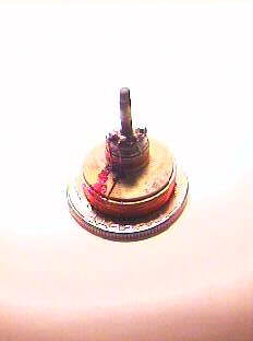
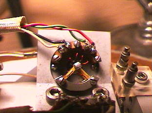
The Westrex coil freshly rewound. The feedback coil is the small red coil at the top, and the drive coil is the pinkish coilst the bottom. The coil is sitting on a US dime to show aproximate size. The feedback coil is 45 gauge wire, and it's DC resistance is 12 ohms. The Drive coil is 39 gauge wire, and its DC resistance is 11 ohms. There are two layers of wire on the feedback coil, and four layers on the drive coil. The winding is done by hand with the aid of a microscopse.
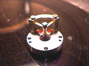
The coil is mounted in it's mount. The drive winding extends below the mount, and the feedback windings are at the same level as the lower portion of the mount. The two v-shaved springs allow the coil to move up and down.
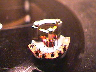
The bakelite block holds the braid wires, much like the wires in speakers, and the braid wires are soldered to the terminal block on the coil. Two wires are for the drive coil, and two for the feedback coil.
The bakelite block is mounted on the coil mount and the coil is now ready to be attached to the head block.
While working on the coils, the head should be demagnitized, and then remagnitized after re-assembly.
Since I don't have that luxery, when I remove the coil, I close the magnetic field, this time with drill bits, to keep the magnet from deteriorating.
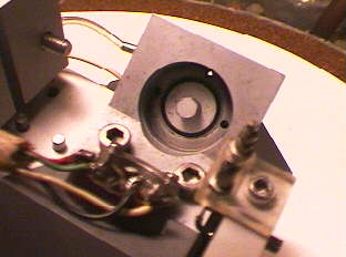
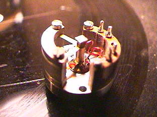
The head assembly with the coil out. You can see the gap where the coil goes, and the post that extends into the center of the feedback coil.
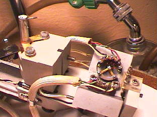
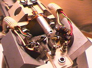
The head assembly with the coil installed. The wiring is attached for the drive and feedback circuits, red & green for dirve, and black & white for feedback.
The head assembly showing the torque tube tilted back. The tube is ready to be returned to it's normal position, and the links attached to the coils.
The torque tube is returned to it's original position, and bolted down. The links are soldered to the coils with silver solder.
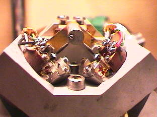
Front view of torque tube. Links are soldered to the tops of the coils. Notice the 45 / 45 degree system. One coil drives the torque tube at a 90 degree angle from the other coil, therefore making the stereo signal in one groove.
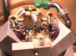
Front view with stylus installed. The stylus is made of saphire or ruby, and has a small heating coil on it's shaft. A terminal block is now blocking your view of the links, and used to supply heater current to the stylus.
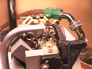
The advanced ball (right) and suction tube (left) are installed. The suction tube vacuums the chip (the part of the groove cut away) off the record.
The advanced ball rides on the uncut surface of the record a few turns before the stylus cuts the groove, and is used to regulate groove depth.
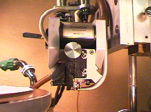
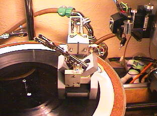
The completed head assembly mounted on the scully lathe.
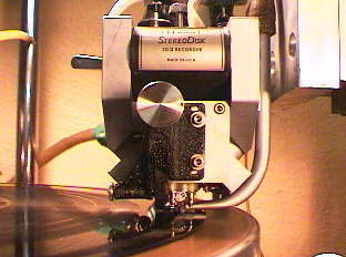
The first test cut. Now begins the tweeking process.
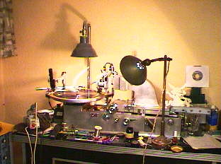
The aftermath of the coil rewinding and re-assembly. The head blew during an industrial recording (DS-003 DJ Freak on Deadly Systems Records) at about 8:30pm Friday the 6th, and I had the coil out by nine.
I had the first layer of wire done about 10:30, and then went to bed. Another two hours of careful winding, and the coil was completed by noon Saturday. The head re-assembly only takes about an hour, but the tweeking can take all day.
 Send a message to the Aardvark crew